Read about Flocx’s current project, a battery-saving WIFI+MQTT-enabling cheap smoke-detector here: https://blog.flo.cx/2018/08/ikea-diy-smart-smoke-detector/
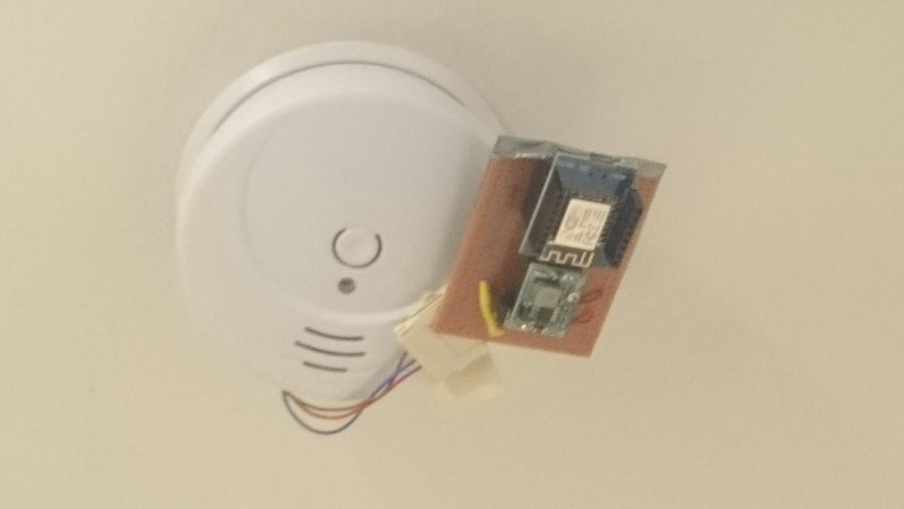
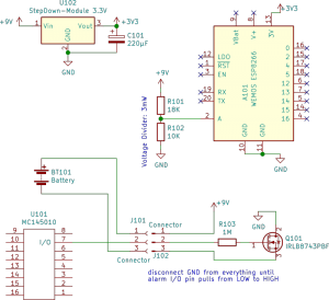
I wanted to do the same thing for my flat, but instead of using the IKEA one, I ordered two cheap 7€ SmartWares detectors from Amazon with 9V batteries that are advertised to give 5yrs battery life and otherwise identical hardware. Also instead of µPython I used Sming and C++. Just for the fun of it, I also added a voltage divider that measures the battery voltage at the time of alarm.
You can find my firmware on GitHub.
Todo for the future: motivate someone to do this for realraum. ;->
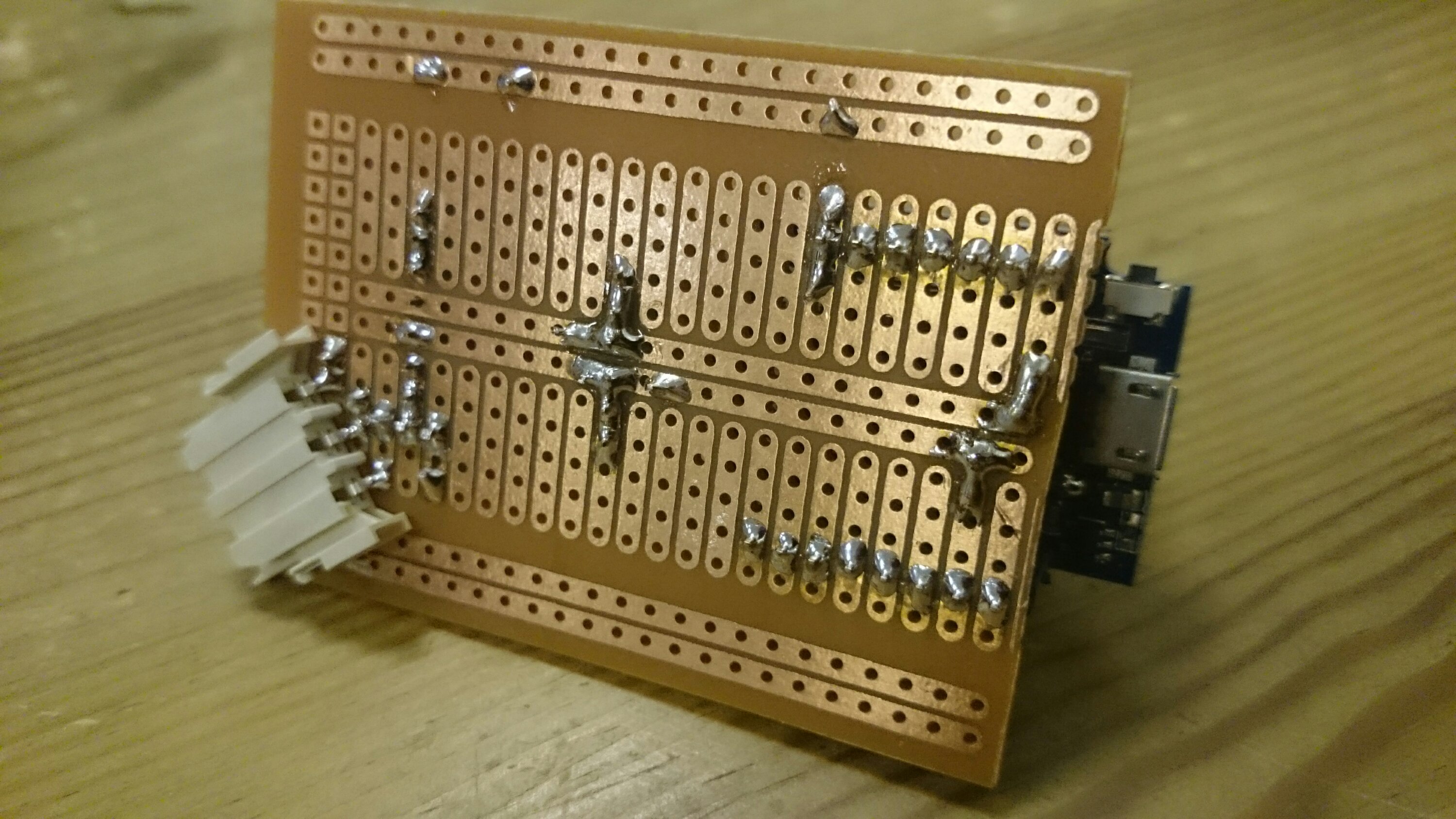
Since all 9V smoke-detectors ICs basically use the same pinout with an I/O-function on pin 7 that pulls LOW when no smoke is detected and HIGH on alarm, they are all equally easy to mod. The SmartWares are smaller than the IKEA ones though, so I did not even attempt to fit everything inside the case. More accessibility traded for lower WAF :)
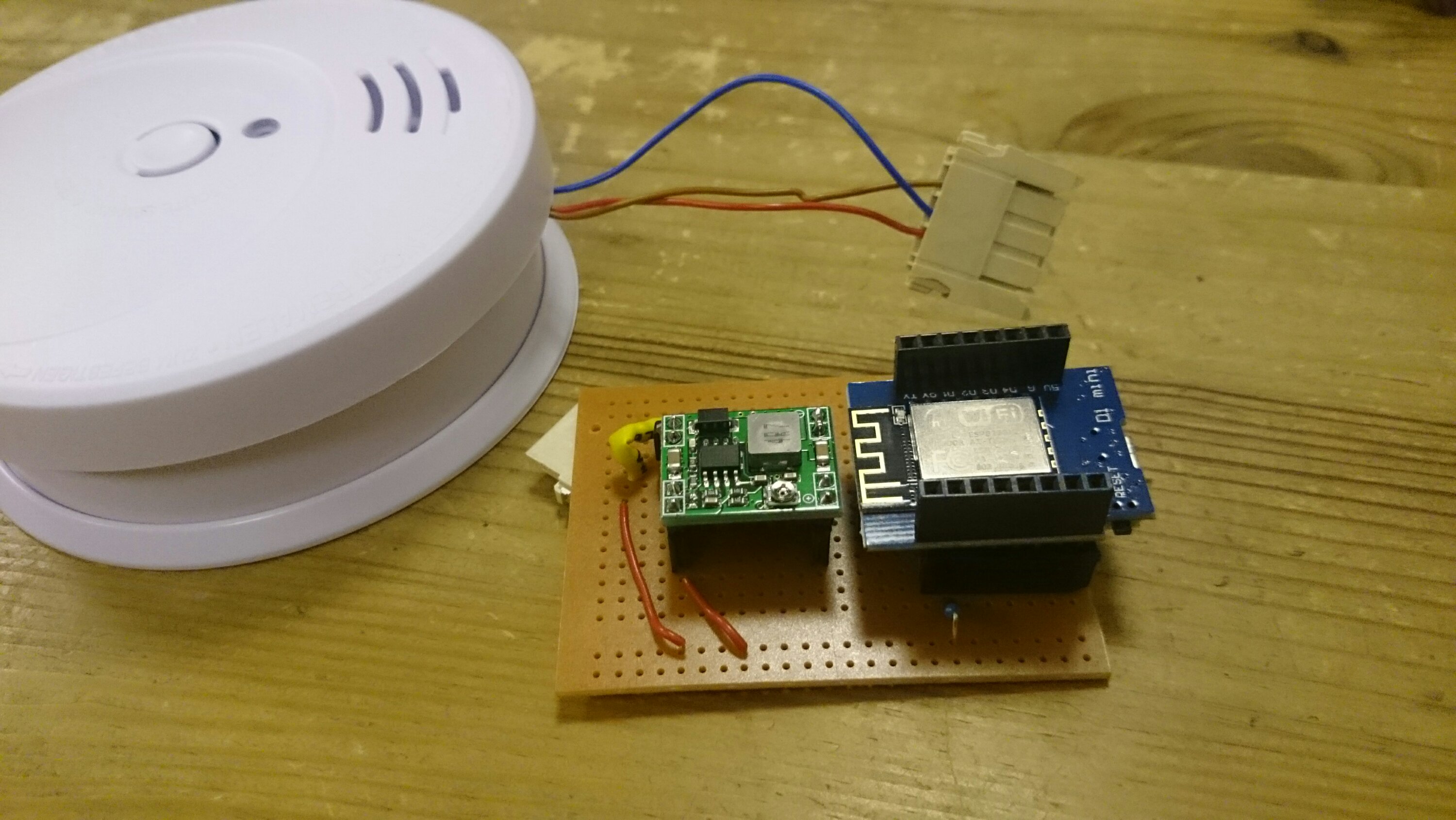
Note that there are 3V Lithium 10yrs battery life smoke detectors out there, which work a bit differently. For once, the ESP8266 does not run with 3.0V but needs true 3.3V, so at the very least you will need a cheap and tiny boost converter from AliExpress. Furthermore, they do not use a CS2105G0 based chip but a PIC which might not have an pin as CS2105G0-I/O-pin configured.
A word of warning: In order to conserve the battery, the circuit disconnects the whole GND when no smoke is detected. Thus GND and 3V3 of the ESP8266 may be short-circuited through the unpowered buck-converter, depending on your component. So just to be safe, remove the Wemos from the circuit before connecting it via USB.