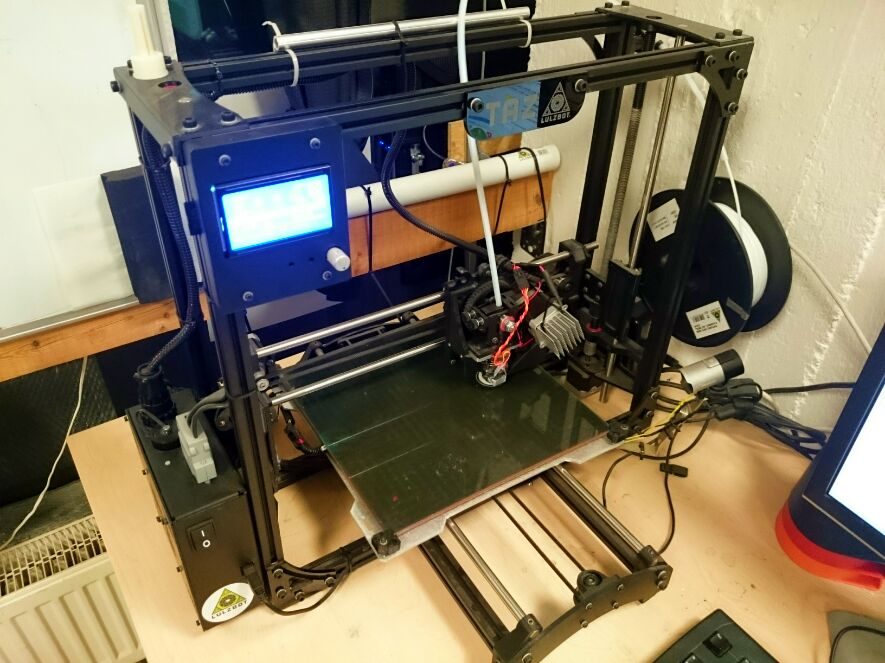
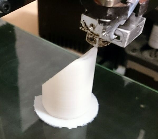
Around the end of Februar 2016 prints with our trusty only 11 months old TAZ4 3D Printer started to fail. Specifically the extruder just stopped extruding mid-print, while everything else was working along as if nothing had happened.
After some investigation, we discovered the problem, the extruder stepper motor was getting waaayyy tooo hot. Each time, about 10 to 15 minutes into a print, the extruder/feed stepper would reach 91°C and just stop moving. As no more filament was being extruded, prints were getting ruined.
Fixing It – First Attempts
First I ran a print with the filament removed, the filament tension mount relaxed in order to reduce any resistance the stepper might encounter. Still it overheated. Obviously we tried attaching a heatsink, but of course that just bought a few extra minutes.
My first idea was to trim the micropotis on the controller board and reduce the motorcurrent. Alas, there were no potis to be found. Then equinox suggested it might be a mechanical problem since everything was working fine the last eleven months.
So we took the extruder apart twice. Second time around an hour later, we discovered that the M10 nut of the bolt conveying the filament which has the big cog on it’s other side, was way too tight. Presumably someone wanted to improve things by tightening the screw.
The result being, that the washer pressed on the bearing and put the brakes on the extruder motor.
Additionally I discovered that the screw afixing the steppershaft to the PLA cogwheel was loose. Possibly the hot motor softened the PLA enough for the shaft to slip through and cause the motor to turn by itself.
Sadly, none of these fixed solved our problem. Our NEMA17 still overheated, with 90°C being far outside it’s absolute maximum rating of 60°C (Specs) and even further away from the 42°C operating temperature reported on the internet.
Fixing It – Delving into the firmware.
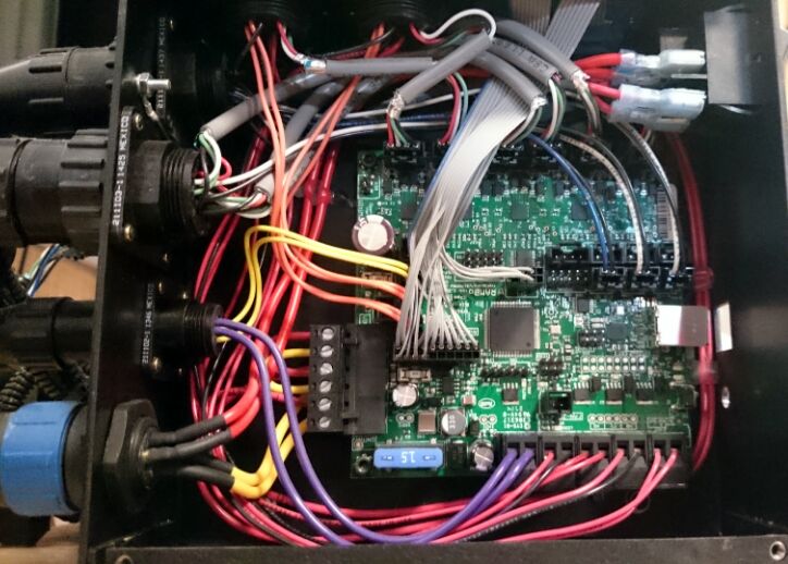
Returning to my first idea, I found out that the Rambo1.3L controller board used by the TAZ4 does allow one to adjust the motor currents. It actually uses a digital potentiometer, an SPI connected AD5206 chip, to adjust the current limiting reference voltage for the stepper drivers. Cool stuff, the firmware can actually adjust the stepper current. Allowing the user to either change values with GCODE commands M907 and M908 or by changing DIGIPOT_MOTOR_CURRENT #define in Configuration_adv.h and recompiling.
I thoroughly tested various settings but to my surprise, there did not seem to be any noticeable effect. In fact, even setting the current to zero, did not affect any of the steppers at all.
The TAZ4 Marlin Firmware comes with it’s own SPI Arduino library, so I tried that as well as the newest version. No difference.
Somewhere at this point, bug hunting went on so late into the night that I even started hallucinating bugs in the Marlin Firmware that weren’t really there.
Fixing Other Stuff.
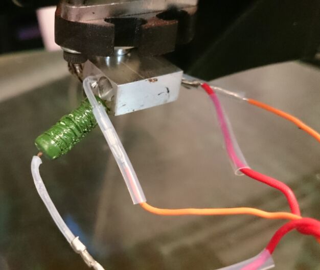
During testing we also discovered, that the extruder would not heat up. A problem we quickly traced to the heating resistor which basically crumbled in my hand when I inspected it. This was probably a result of our printing experiments with Bridge Nylon at 335°C and quickly fixed as Lulzbot thankfully uses a common resistor that can easily be ordered online.
Fixing It – Delving into the hardware.
The next step was looking up the AD5206 datasheet and RAMBO Schematics, dusting off my OpenLogicBench analyser and sniff that SPI bus. This was not without problems, as the SPI signal was barely recognizable on an oscilloscope as long as the display was connected to the SPI bus as well. The logic analyser could not even differentiate HIGH from LOW. After disconnecting it, we had much more luck decoding signals on the oscilloscope but not with the logic analyser.

After many hours of experimenting, I finally concluded that the AD5206 was shot. No matter what command was sent, the reference voltages generated would remain the same. The Z and E axis was always driven with the maximum current. On the Z axis, that was ok, since the current is split between two motors. For the E axis, it was the cause of our overheating problem.
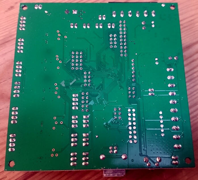
Inspecting the backside of the board, one can even clearly see where the high current going through the E0 and Z stepper drivers blackened the backside of the board. (two chip-sized dark spots)
Seeing it as a nice opportunity to test some SMD soldering skills before replacing the whole board, I ordered some AD5206 chips.
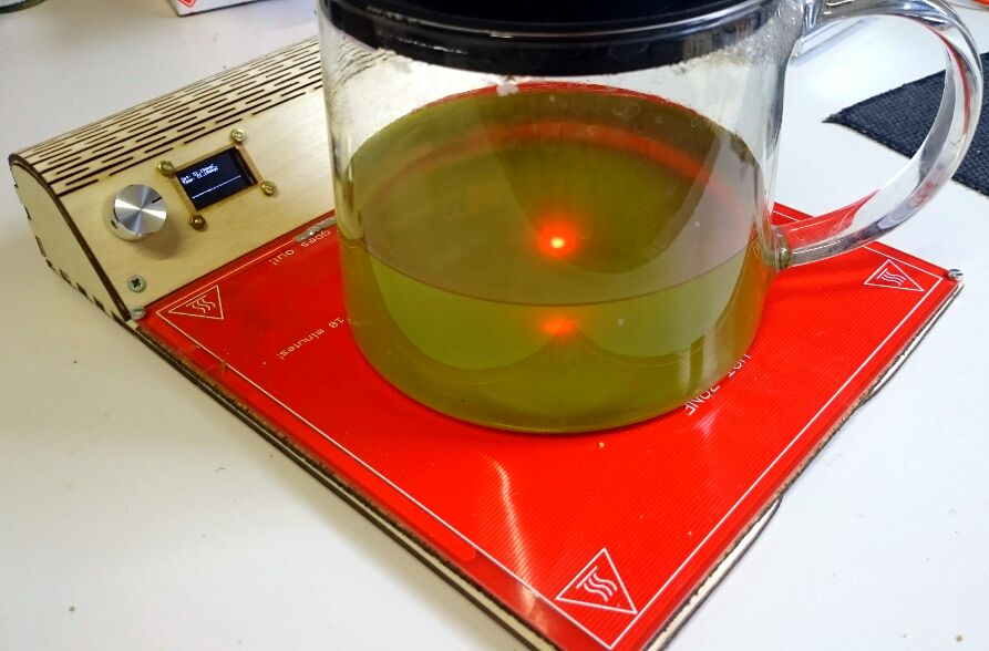
On of our members, Laszlo, lent realraum his Hot Air Solderer. In order to make things go even smoother, I re-purposed our old RepRap heat-bed as a Teensy and PID controlled, SMD preheating plattform. (With OLED Graph and WS2812b LEDS of course)
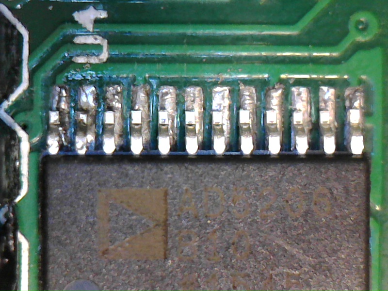
As our USB microscope revealed, my soldering work turned out to not be picture perfect, mostly due to difficulties cleaning the pads of excess solder. All pins had good connection however and thus I moved on to testing.
Unfortunately it turned out, that, while the AD5206 clearly reacts to SPI commands now and the reference voltages could be changed with GCODE commands, I could only affect change in a range of 0 to 9mV for E0 and E1 rather than the full necessary range of 0 to 1.8V. Funny enough, the values for the X,Y,Z axes were still approximately correct, but similarly could only be affected in a range of 9mV. Obviously something else was broken or broken as well.

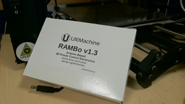
Fixing It – Ordering a replacement Rambo1.3L
Comparing prices including customs tax, we ordered from the UltiMachine online shop. The board was promptly shipped and arrived in Austria only a few days later. Not grounds for immediate joy however, as Austrian customs is currently understaffed and decided to not even look at our parcel for four !!! whole weeks. <conspiracy fun>I wonder if most of the customs officers were sent on holiday during the Obama EU visit, in order to make some roundabout statement about how, if only people would stop their valid fear of american food products and accept TTIP into their bodies and hearts, their parcels would arrive much faster. (No I obviously don’t really believe that, but it’s a fun idea)</conspiracy fun>
Yesterday, the board finally arrived and got installed.
Today, after some tests I was very pleased with the E0 stepper temperature staying at a comfortable 45°C now. However X and Y steppers were getting slightly hotter than before. (60°C after 1h of printing.) Of course we don’t want to lower the values too much as it would impact acceleration. After some fiddling, I went with what should be 0.275A less current for those steppers and set the values below in Configuration_adv.h.
After a bit of testing I’m not entirely convinced that all the settings reach the AD5206 correctly each and every time. Might be the display connected via long wires in a star configuration of the same SPI bus is a design issue. Likely a bit more testing is still required.
Still, after 1.5 months we’re finally able to 3D print again. Celebrations and careful printing may commence :-)
// Motor Current setting for digital trimpot

// Order: X,Y,Z,E0,E1 according to DIGIPOT_CHANNELS in pins.h

#define DIGIPOT_MOTOR_CURRENT {120,120,240,135,135} // Values 0-255 (RAMBO 135 = ~0.75A, 185 = ~1A)